Understanding Bathroom Exhaust Fan Wiring
A bathroom exhaust fan plays a crucial role in removing moisture and odors from the bathroom, creating a healthier and more comfortable environment. Understanding the wiring of this essential appliance is crucial for proper installation, maintenance, and troubleshooting. This guide will delve into the basics of bathroom exhaust fan wiring, providing you with the knowledge to confidently navigate this aspect of home improvement.
Basic Components
The wiring system of a bathroom exhaust fan consists of several key components:
- Fan Motor: The heart of the exhaust fan, the motor is responsible for powering the fan blades, creating airflow to expel air from the bathroom.
- Switch: A simple on/off switch controls the flow of electricity to the fan motor, allowing you to activate and deactivate the fan as needed.
- Electrical Wiring: The electrical wiring provides the pathway for electricity to flow from the power source to the fan motor. This wiring typically consists of two or three insulated wires, each carrying a specific type of electrical current.
Electricity Flow
When you flip the switch to turn on the bathroom exhaust fan, electricity follows a specific path:
- Power Source: Electricity originates from the main power source, usually a circuit breaker in your electrical panel.
- Switch: The switch acts as a gatekeeper, controlling the flow of electricity to the fan motor. When the switch is turned on, it completes the circuit, allowing electricity to pass through.
- Electrical Wiring: Electricity travels through the electrical wiring, carrying the power from the switch to the fan motor.
- Fan Motor: The fan motor receives the electrical current, converting it into mechanical energy to spin the fan blades.
- Exhaust: As the fan blades rotate, they draw air from the bathroom, expelling it to the outside through the exhaust vent.
Types of Wiring Diagrams
Bathroom exhaust fan wiring diagrams provide a visual representation of the electrical connections within the system. Different types of diagrams are used depending on the complexity of the wiring setup:
- Single-Pole Diagram: The simplest type of wiring diagram, a single-pole diagram uses a single switch to control the fan motor. This is the most common setup for basic bathroom exhaust fans.
- Three-Way Diagram: Three-way wiring diagrams utilize two switches to control the fan motor. This setup allows you to turn the fan on or off from two different locations, which can be convenient in larger bathrooms or when the fan switch is located far from the fan itself.
Common Wiring Configurations

Bathroom exhaust fan wiring diagram – Bathroom exhaust fans can be wired in different ways to suit various needs and preferences. Understanding these configurations is crucial for selecting the right wiring setup and ensuring proper fan operation.
Single-Pole Wiring
The simplest wiring configuration is single-pole wiring. This setup involves connecting the fan directly to a single switch, providing basic on/off control. It’s a straightforward option, ideal for fans with minimal functionality.
| Configuration | Wiring Diagram | Description | Advantages | Disadvantages |
|---|---|---|---|---|
| Single-Pole | [Image of a single-pole wiring diagram] The diagram shows a single switch connected to the fan, with power coming from the electrical panel. | The fan is directly connected to a single switch, providing basic on/off control. | Simple and straightforward wiring. Cost-effective. |
Limited control options. No automatic operation or timer functionality. |
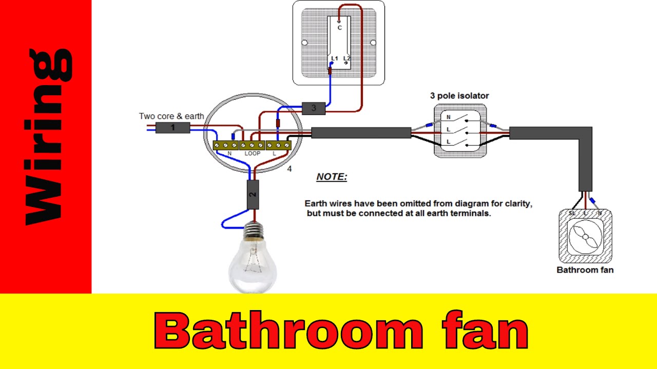
Three-Way Wiring, Bathroom exhaust fan wiring diagram
Three-way wiring offers more flexibility by allowing fan control from multiple locations. This configuration utilizes two switches that work together to control the fan, often used for bathrooms with multiple entrances.
| Configuration | Wiring Diagram | Description | Advantages | Disadvantages |
|---|---|---|---|---|
| Three-Way | [Image of a three-way wiring diagram] The diagram shows two switches connected to the fan, with power coming from the electrical panel. The switches are wired in a way that allows either switch to control the fan. | Two switches control the fan, enabling operation from multiple locations. | Flexibility in fan control. Convenient for bathrooms with multiple entrances. |
More complex wiring compared to single-pole. Requires careful installation and troubleshooting. |
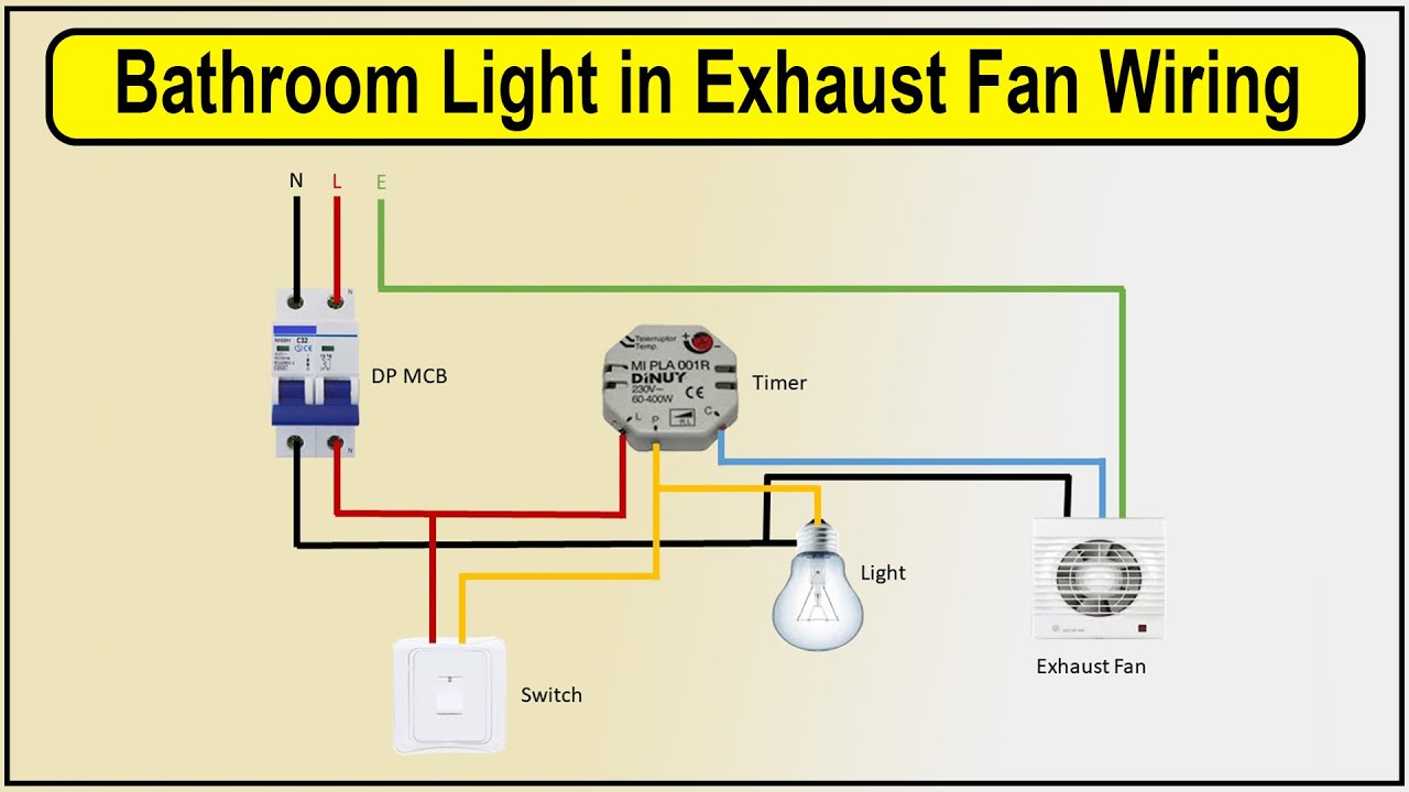
Timer-Controlled Wiring
Timer-controlled wiring allows the fan to run for a predetermined duration after it’s turned on, automatically shutting off after the set time. This configuration is useful for ensuring adequate ventilation after showering or bathing, preventing moisture buildup.
| Configuration | Wiring Diagram | Description | Advantages | Disadvantages |
|---|---|---|---|---|
| Timer-Controlled | [Image of a timer-controlled wiring diagram] The diagram shows a timer switch connected to the fan, with power coming from the electrical panel. The timer switch allows the fan to run for a set duration after it’s turned on. | A timer switch controls the fan’s operation, automatically shutting off after a set time. | Automatic ventilation for a specific duration. Helps prevent moisture buildup and mold growth. |
Requires a timer switch, adding to installation cost. May not be suitable for continuous ventilation needs. |
Humidity-Sensing Wiring
Humidity-sensing wiring automatically turns the fan on when humidity levels rise, ensuring proper ventilation and moisture control. This configuration is ideal for bathrooms with frequent moisture buildup, providing continuous ventilation without manual intervention.
| Configuration | Wiring Diagram | Description | Advantages | Disadvantages |
|---|---|---|---|---|
| Humidity-Sensing | [Image of a humidity-sensing wiring diagram] The diagram shows a humidity sensor connected to the fan, with power coming from the electrical panel. The sensor detects humidity levels and automatically turns the fan on when they exceed a set threshold. | A humidity sensor automatically turns the fan on based on humidity levels, providing continuous ventilation. | Automatic moisture control and ventilation. Energy-efficient, only operating when needed. |
Requires a humidity sensor, adding to installation cost. May not be suitable for bathrooms with low humidity levels. |
Troubleshooting Wiring Issues: Bathroom Exhaust Fan Wiring Diagram
Even the most well-installed bathroom exhaust fan can experience wiring problems over time. These issues can range from minor annoyances to safety hazards, so it’s important to understand how to diagnose and fix them. This section will guide you through common wiring problems, troubleshooting techniques, and preventative measures to keep your bathroom exhaust fan running smoothly.
Common Wiring Problems
Wiring problems in bathroom exhaust fans can stem from various causes, including loose connections, faulty switches, and damaged wires. Identifying these issues early is crucial to prevent potential safety hazards and ensure proper ventilation.
- Loose Connections: Over time, vibrations and heat can loosen wire connections at the fan motor, switch, or junction box. This can lead to intermittent operation, flickering lights, or complete failure of the fan.
- Faulty Switches: The switch controlling your bathroom exhaust fan can malfunction due to wear and tear, causing the fan to turn on or off unexpectedly. This can be particularly dangerous if the fan stops working during a shower, leading to moisture buildup.
- Broken Wires: Physical damage to wires, often caused by rodents, moisture, or improper installation, can lead to a complete loss of power to the fan.
Diagnosing Wiring Issues
Diagnosing wiring problems in a bathroom exhaust fan requires a systematic approach, starting with visual inspection and moving on to electrical testing using a multimeter.
- Visual Inspection: Start by carefully inspecting the fan, switch, and wiring for any visible signs of damage, loose connections, or corrosion. Look for frayed wires, burnt insulation, or any signs of water damage.
- Continuity Test: Use a multimeter to check the continuity of the wiring. This test verifies that the electrical path is complete and unbroken. To perform a continuity test, set the multimeter to the “ohms” setting and touch the probes to the ends of each wire. A reading of 0 ohms indicates a good connection.
- Voltage Test: Use the multimeter to measure the voltage at the fan motor and switch. This test verifies that the correct voltage is reaching the fan. Set the multimeter to the “volts” setting and touch the probes to the terminals of the motor or switch. A reading of 120 volts indicates that power is reaching the device.
Resolving Wiring Issues
Once you’ve identified the source of the wiring problem, you can proceed with the necessary repairs.
- Tighten Loose Connections: If you find loose connections, carefully tighten them using a screwdriver or wire strippers. Ensure that the connections are secure and that the wires are not touching each other.
- Replace Faulty Switches: If the switch is malfunctioning, replace it with a new one. Ensure that the new switch is rated for the appropriate voltage and amperage.
- Repair or Replace Damaged Wires: If the wires are damaged, you may need to repair them by splicing in a new section of wire. Alternatively, you can replace the entire wiring run. Ensure that you use wire with the correct gauge and insulation for the application.
Preventing Future Wiring Problems
Taking preventive measures can help to minimize the risk of future wiring problems in your bathroom exhaust fan.
- Use Proper Wire Gauge: Always use wire with the correct gauge for the amperage of the fan motor. Using wire that is too thin can lead to overheating and damage.
- Secure Connections Tightly: Ensure that all wire connections are tightly secured using wire nuts or terminal blocks.
- Inspect Regularly: Periodically inspect the fan, switch, and wiring for any signs of damage or wear. This can help to catch problems early before they become serious.
Understanding a bathroom exhaust fan wiring diagram is crucial for ensuring proper ventilation and preventing moisture buildup, especially in small spaces. If you’re considering a small walk-in shower bathroom ideas , a well-functioning exhaust fan is essential for maintaining a comfortable and healthy environment.
By carefully studying the wiring diagram, you can ensure that your fan is properly installed and operates efficiently, contributing to a more enjoyable bathroom experience.
Understanding a bathroom exhaust fan wiring diagram is crucial for any DIY project, especially if you’re planning to replace your existing fan. If you have a Nutone fan, you might want to consider a nutone bathroom fan replacement for improved ventilation and noise reduction.
The wiring diagram will guide you through the process of connecting the new fan to the existing electrical system, ensuring a safe and functional installation.
